购买咨询热线/Phone:
 邮箱/Email:
 地址:
地址:Description
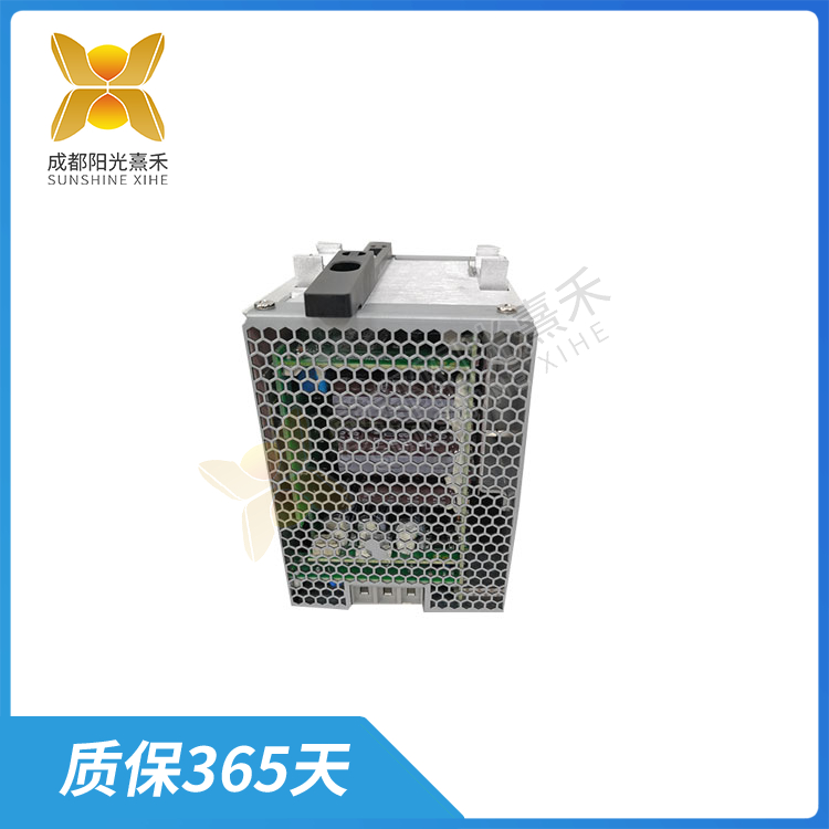
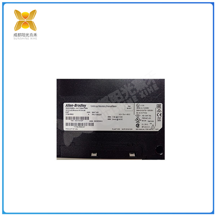
1756-RM2 规格参数工业计算机
1756-RM2规格参数工业计算机只需一个普通网卡即可通过以太网LAN从PLC主站接收数据。 PLC主张由一台AC500系列PLC和相应的外围设备组成,并放置在中央控制室内。 PLC主站从分布式I / O接收数据, 执行相关处理和控制,并通过标准工业以太网TCP / IP通信模块(TB521-ETH)以10 mbit / m的传输速率将其传输到工业控制计算机s,介质是双重屏蔽的。
中央处理器(CPU)由一个控制器、一个运算器和一个寄存器组成,它们集成在一个芯片中。CPU通过数据总线、地址总线、控制总线和电源总线与存储器、输入输出接口、编程器和电源相连。1756-RM2规格参数
1756-RM2规格参数1. 编程操作
(1)方案编制。检查PLC和计算机之间的连接是否正确,计算机的RS232C端口是否连接到PLC以及的范围线和转换器连接:保持PLC处于“关机”状态;计算机和PLC上有电源。
(2)编程操作。
1打开GX Developer编程软件,创建一个新项目并命名。
(2)使用梯形图编程的方法,编辑并保存如图1所示的梯形图程序。
(3)程序的传送。
程序的编写。将编辑后的程序写入PLC用户内存中,并进行检查。
2节目阅读。 PLC用户存储器中的程序通过[Read In]操作读入计算机,然后进行检查。
(3)程序检查。在检查上述程序的过程中,只有当计算机两端的程序相对正确时,才能认为程序传输正确,否则应查明原因并重新传输。
2. 运行操作
程序传输到PLC用户内存后,程序可按以下方式运行。
1根据梯形图程序,将PLC的输入/输出连接到部件的输入信号。 PLC的输入/输出编号和描述如表1所示。
(2)打开PLC操作开关,PLC面板上的运行灯指示程序已投入运行。
控制程序应与控制程序相结合,以操作输入信号,并观察不同输入状态下输入/输出指示灯的变化。如果输出指示灯的状态与程序控制要求一致,则表示程序正常运行。
1、常见的故障现象
当PLC的rs-485端口通过非隔离的pc / ppi电缆连接到计算机时,plc和plc之间的连接,或plc和逆变器之间的通信,触摸屏等,通讯端口损坏。更常见的损害赔偿如下:
(1)R1或R2烧坏,Z1、Z2、SN75176完好。这是由于通过R1或R2、桥式整流器、Z1或Z1对地的瞬态干扰电流较大,Z1和Z2能承受*10A电流的冲击,电流对R1或R2产生的瞬态功率为102*10=1000W,当然会烧坏。
(2)sn75176损伤,R1,R2,Z1,Z2均处于良好状态。这可能是由于静电冲击或暂态过电压速度比Z1,Z2动作速度快,静电无处不在,只有人的模式也会产生±15 kV的静电。
(3)z1或z2,sn75176损坏,r1和r2完好无损。这可能是由于高电压和低电流瞬态干扰电压击穿z1或z2和sn75176。由于电流小且产生时间短,因此r1和r2不会燃烧。
2、故障的原因分析
通过1中的分析可知,造成PLC接口损坏的主要原因是瞬态过电压和静电。瞬态过电压和静电产生的原因是多方面的。例如,由于PLC中的24V电源和5V电源为公共接地,当与其它设备混合时,24V电源的输出端可能会引起接地电位的变化。共模电压出允许范围。因此,EIA-485标准要求每个RS485接口的信号通过低电阻线连接,以确保每个节点的接地电位相等,并消除接地循环。
(1)当未隔离的连接电缆接入线路时,在两端具有不等电位的电路中存在许多电感、电容和其他器件,因此在插拔时不可避免地会出现瞬态过电压或过电流。基于该考虑,当通信连接器被插入时,设备被尽可能地切断。
(2)连接到rs-485总线的其他设备产生的瞬态过电压或过电流也会流入plc。连接到总线的设备越多,产生的瞬态过电压就越多。
(3)雷电是通信线路长或户外架空线路时必须考虑的干扰。雷电是主要的自然干扰源。闪电造成的干扰可以传播到几千公里以外。雷电干扰的时域波形叠加在随机脉冲背景下的一个大尖峰脉冲上。这种能量密集的尖峰脉冲不可避免地会引起线路过电压,损坏与PLC等通信网络相连的设备。应避免或减少损坏程度和损失。
1756-RM2 规格参数工业计算机
1756-RM2 Specifications Industrial computers need only a common network card to receive data from the PLC master station over an Ethernet LAN. The PLC is composed of an AC500 series PLC and the corresponding peripheral equipment, and is placed in the central control room. The PLC master station receives data from distributed I/O, performs related processing and control, and transmits it to the industrial control computer s at a transmission rate of 10 mbit/m via the standard Industrial Ethernet TCP/IP communication module (TB521-ETH), the media is doubly shielded. Twisted
The central processing unit (CPU) consists of a controller, an arithmetic unit, and a register, which are integrated into a chip. The CPU is connected to the memory, input/output interface, programmer and power supply via the data bus, address bus, control bus and power supply bus. 1756-RM2 Specifications
1756-RM2 Specifications 1. Programming operations
(1) Program preparation. Check that the connection between the PLC and the computer is correct, that the RS232C port of the computer is connected to the PLC and that the range line and converter are connected: keep the PLC in the “off” state; There is a power supply on the computer and PLC.
(2) Programming operation.
1 Open the GX Developer programming software, create a new project and name it.
(2) Use the ladder diagram programming method to edit and save the ladder diagram program as shown in Figure 1.
(3) Transmission of the program.
Programming. The edited program is written into PLC user memory and checked.
2 Program reading. Programs In the PLC user memory are Read into the computer by the [Read In] operation and then checked.
(3) Program check. In the process of checking the above programs, only when the programs on both ends of the computer are relatively correct, can the program be considered to be correctly transmitted, otherwise the cause should be identified and re-transmitted.
2. Run the operation
After the program is transferred to the PLC user memory, the program can be run in the following manner.
1 Connect the input/output of the PLC to the input signal of the component according to the ladder diagram program. The input/output numbers and descriptions of PLC are shown in Table 1.
(2) Open the PLC operating switch, and the running light on the PLC panel indicates that the program has been put into operation.
The control program should be combined with the control program to operate the input signal and observe the change of the input/output indicator light in different input states. If the status of the output indicator is consistent with the program control requirements, it indicates that the program is running normally.
1. Common fault phenomena
When the PLC’s rs-485 port is connected to the computer through a non-isolated pc/ppi cable, the connection between the plc and the plc, or the communication between the plc and the inverter, the touch screen, etc., the communication port is damaged. More common damages are as follows:
(1) R1 or R2 is burnt out, Z1, Z2 and SN75176 are intact. This is because the transient interference current through R1 or R2, bridge rectifier, Z1 or Z1 to the ground is large, Z1 and Z2 can withstand the impact of *10A current, the current generated by R1 or R2 transient power is 102*10=1000W, of course, it will burn out.
(2) sn75176 damage, R1, R2, Z1, Z2 are in good condition. This may be due to static shock or transient overvoltage speed faster than Z1, Z2 operation speed, static electricity everywhere, only the human mode will produce ±15 kV static electricity.
(3) z1 or z2, sn75176 damaged, r1 and r2 intact. This may be due to high voltage and low current transient interference voltage breakdown z1 or z2 and sn75176. Due to the small current and short generation time, r1 and r2 do not burn.
2. Cause analysis of failure
According to the analysis in 1, the main causes of PLC interface damage are transient overvoltage and static electricity. There are many reasons for transient overvoltage and static electricity. For example, because the 24V power supply and 5V power supply in the PLC are common ground, the output of the 24V power supply may cause a change in the ground potential when mixed with other equipment. Common-mode voltage out allowable range. As a result, the EIA-485 standard requires signals from each RS485 interface to be connected via low-resistance wires to ensure equal ground potentials at each node and eliminate grounding cycles.
(1) When the unisolated connection cable is connected to the line, there are many inductors, capacitors and other devices in the circuit with unequal potentials at both ends, so there will inevitably be transient overvoltage or overcurrent when plugged in and out. Based on this consideration, when the communication connector is inserted, the device is cut off as much as possible.
(2) Transient overvoltage or overcurrent generated by other devices connected to the rs-485 bus will also flow into the plc. The more devices connected to the bus, the more transient overvoltages are generated.
(3) Lightning is a interference that must be considered when communication lines are long or outdoor overhead lines. Lightning is the main source of natural interference. The disturbance caused by lightning can travel thousands of kilometers. The time domain waveform of lightning interference is superimposed on a large spike pulse in a random pulse background. This energy-dense spike will inevitably cause line overvoltage and damage equipment connected to communication networks such as PLCS. Damage and loss should be avoided or minimized.
 购买咨询热线/Phone:18859254943
- 邮箱/Email:sales@ygdcs.com
- 地址:成都高新区天益街北巷52号附14号2层