微软WINDOWS 2000 作为系统操作平台;System 1作为操作软件,版本5.00;RackConfiguration Software作为工程师组态软件,版本3.60;组态用户程序。均安装在操作站(工程师站)上。
某夏天的一天,操作站突然显示机组部分振动值、位移值为0。经检查,共有4块振动位移卡(3500/40M)和1块键相卡(3500/25),有的状态指示灯全熄灭,或闪烁或变红报警,证实卡件坏。共计8个振动回路,5个位移回路,2个键相回路失灵。其中全部振动回路和位移回路参与机组紧急停车联锁。
故障发生后,有8个振动回路和1个转速回路仍然正常工作,可以判断电源卡、通讯卡没有损坏。机组并未停车,说明继电器卡仍正常工作。(该系统通过继电器卡,送干接点信号给机组停车系统)当天为强雷雨天气,装置区多次发生多次雷电,卡件大面积失灵与雷击时间点吻合,因此雷击应为上述卡件损坏原因。
1、卡件接线端子上信号电缆屏蔽线电缆由室外进入控制室端子柜。屏蔽线与端子柜相接触,如有强电通过时,可能会导致强电进入卡件。但随后检查发现,由于施工原因,一块已烧坏的位移监测卡并未接入的屏蔽线。可以判定该途径非卡件损毁的主要原因。
歧化装置3500系统配有3500/92通讯网关卡一块,作为与PLC通讯,将23个监测数据送给PLC,由操作站显示。某日晨1时许,机组PLC系统操作站监控流程图画面中关于轴系监测部分参数的测量值不再更新。系统操作站其他位号显示正常,联锁系统以及自动控制系统正常。据仪表人员检查,通过收集总结故障位号的共同性,根据故障位号的信号来源均为3500系统与PLC系统之间通过MODBUS协议通讯传输,而PLC与3500系统其他功能正常,所以基本判定为3500系统与PLC系统之间通讯故障所导致。
1、检查3500系统中的MODBUS网关模件(3500/92)以及其他卡件状态指示灯运行情况,发现3500/92的OK灯闪烁(正常情况为常亮)、TX/RX灯熄灭(正常情况为闪烁),其他状态灯为正常。
1. General Electric’s BENTLY 3500 system is a characteristic monitoring system that can reduce operating costs, improve product quality, increase plant safety, and maximize plant availability. The 3500 system can send a variety of data to other systems, and through the support of these data, the quality of the operation judgment is higher. Its function is to monitor the operating state of the unit shaft system online, send the unit’s interlock protection signal to the interlock shutdown system, and communicate with the PLC system.
2. Bentley 3500 system hardware and software configuration
2.1 Hardware Configuration
The hardware part includes: 1 DELL GX270 microcomputer as an operation station and engineer station function. A 3500 frame and card number, specific see Table 1.
2.2 Software Configuration
Microsoft WINDOWS 2000 as the system operating platform; System 1 as the operating software, version 5.00; RackConfiguration Software as engineer configuration software, version 3.60; Configure user programs. They are installed on the operation station (engineer station).
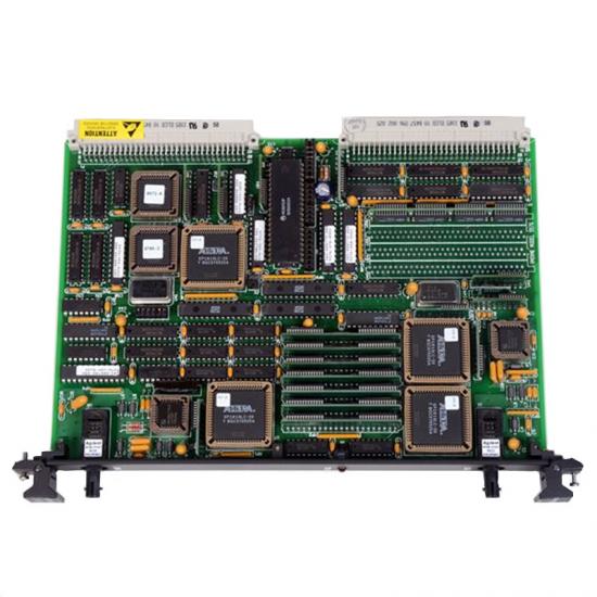
The physical picture of the 3500 detection system is shown in Figure 1:
3. Fault analysis and treatment
3.1 A large area of system card is burned out due to lightning accident
One summer day, the operation station suddenly showed that the vibration value and displacement value of part of the unit were 0. After inspection, there are 4 vibration displacement cards (3500/40M) and 1 key phase card (3500/25), and some status indicators are all out, or flash or turn red alarm, confirming that the card is bad. A total of 8 vibration loops, 5 displacement loops, and 2 key phase loops failed. All vibration circuits and displacement circuits are involved in the emergency shutdown interlock of the unit.
After the fault occurs, 8 vibration circuits and 1 speed loop are still working normally, and it can be judged that the power card and communication card are not damaged. The unit did not stop, indicating that the relay card is still working normally. (The system sends the dry contact signal to the unit parking system through the relay card) on the day of strong thunderstorm weather, multiple lightning occurred in the device area, and the large area failure of the card coincided with the time point of lightning strike, so lightning strike should be the cause of damage to the above card.
This system uses UPS power supply, UPS itself has the isolation function. Compared with other cards, the damaged card has two common ways to connect with the external equipment of the system, which may introduce strong electricity and burn the card.
1. The signal cable shielding cable on the wiring terminal of the card enters the terminal cabinet of the control room from the outside. The shielded cable is in contact with the terminal cabinet. If strong electricity passes through, strong electricity may enter the card. However, the subsequent inspection found that due to construction reasons, a burned-out displacement monitoring card was not connected to the shielding line. It can be determined that this way is not the main cause of card damage.
2. The external monitoring port on the panel of all damaged cards is connected to the KD5000 status detection system. After inspection, the KD5000 system uses non-UPS power supply and does not have strong current isolation function. And there is no protective ground terminal in the wall type three socket used. Strong electricity may enter the card through this way.
3.2 92 Gateway Faults and Analysis
The disproportionation unit 3500 system is equipped with a 3500/92 communication network checkpoint, which communicates with the PLC and sends 23 monitoring data to the PLC for display by the operation station. At about 1 o ‘clock in the morning of a certain day, the measured values of some parameters of shafting monitoring in the monitoring flow chart of the PLC system operation station of the unit were no longer updated. The other digit numbers of the system operation station are displayed normally, and the interlock system and automatic control system are normal. According to the inspection of the instrument personnel, by collecting and summarizing the commonality of the fault bit number, the signal source according to the fault bit number is the communication transmission between the 3500 system and the PLC system through MODBUS protocol, while the other functions of the PLC and the 3500 system are normal, so it is basically determined that the communication failure between the 3500 system and the PLC system is caused.
Troubleshooting is as follows:
First, PLC system
1. The RTU manager module (RTM700B) and other card status indicators in the PLC system are running, and it is found that the OK light in the RTU is steady on (normal state), the TX light is off (normal state is blinking), and the other card indicators are normal.
2, check the RS485 communication cable, after inspection: the signal cable and the joint are tightly welded, and the multimeter test is in good condition.
3. Check the working status of the COM subroutine in the PLC program, and find that the COM program is in a standby state (that is, it is not in a normal working state), activated by the software, and there is no data transmission. Other programs are running normally.
4, PLC control station cold, after the communication program is not automatically activated.
5, replace the RTU manager module (RTM700B) module of the slave station and the master station in the PLC control station, repeat the operation of 3 and 4 steps, and the data transmission between the systems is not restored.
To sum up, the communication problems caused by PLC system and communication cable fault are basically eliminated.
2. 3500 system
1. Check the operating status of the MODBUS gateway module (3500/92) and other card status indicators in the system 3500, and find that the OK indicator of 3500/92 is blinking (normally steady), the TX/RX indicator is off (normally blinking), and other status indicators are normal.
2, the card after hot plug, restart, still does not work normally.

购买咨询热线/Phone:18859254943
邮箱/Email:sales@ygdcs.com
地址:成都高新区天益街北巷52号附14号2层


 购买咨询热线/Phone:
 邮箱/Email:
 地址:
地址:


