Description
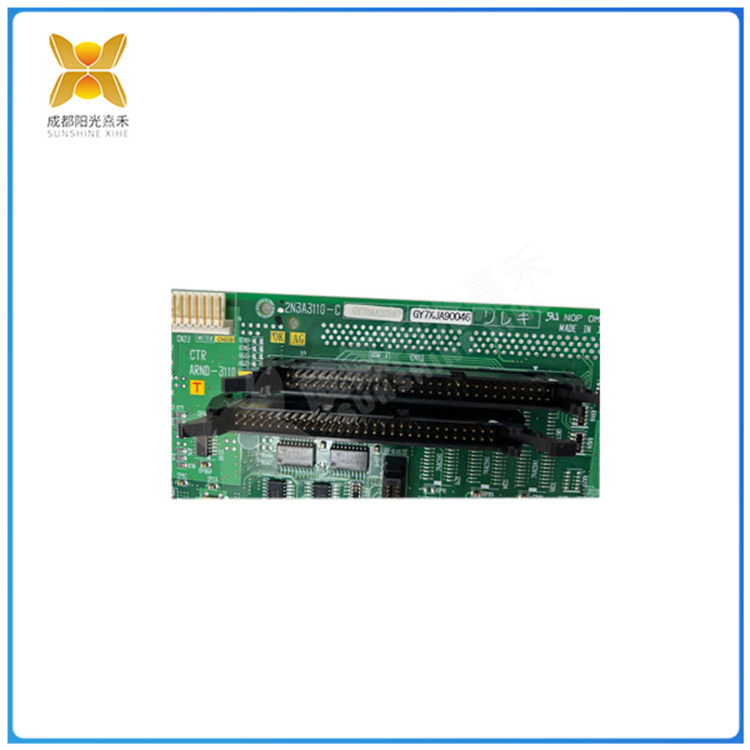
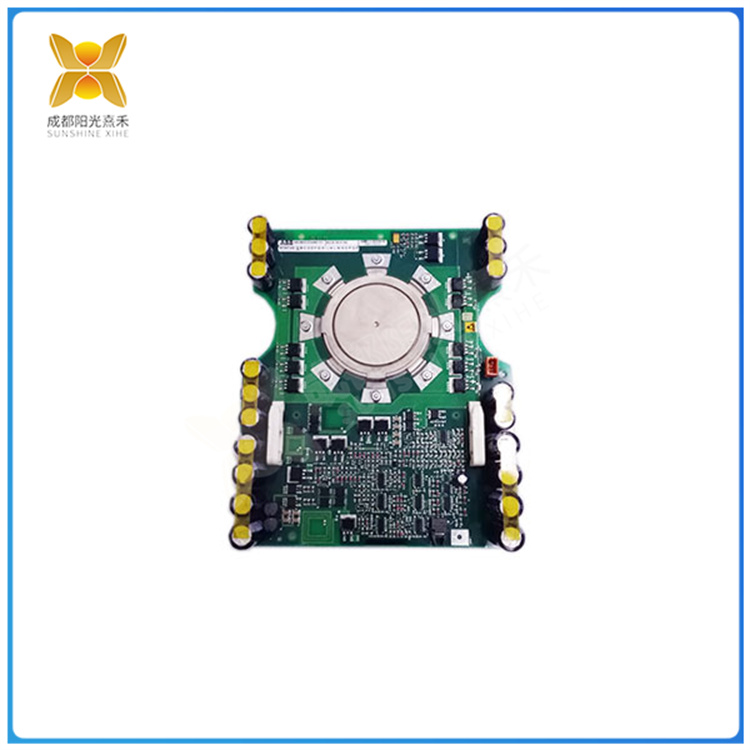
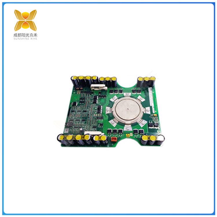
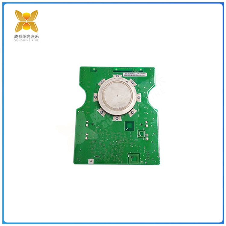
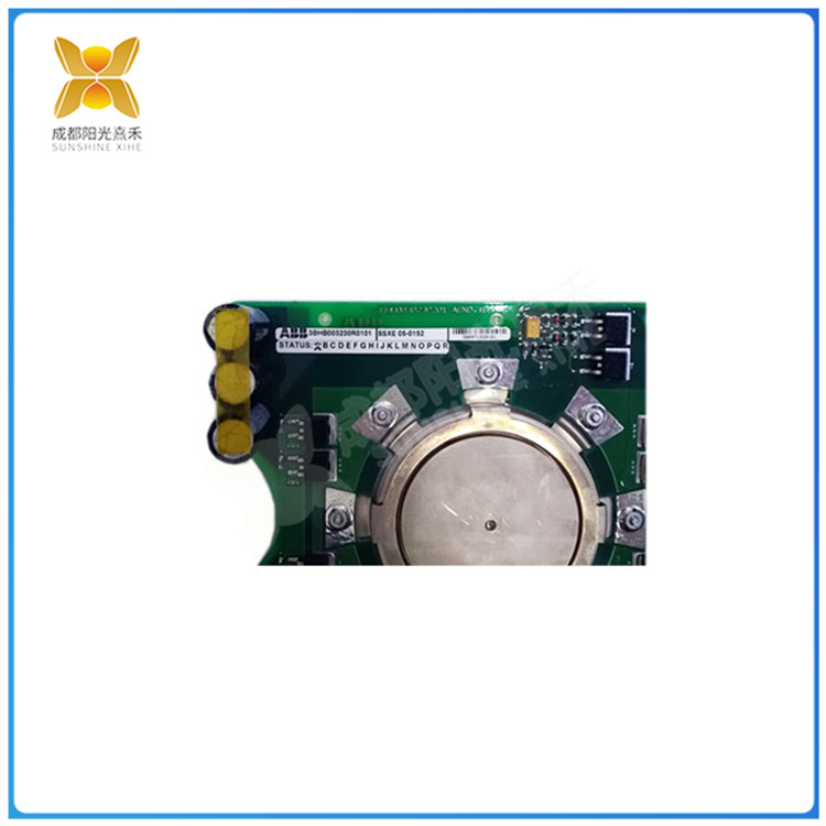
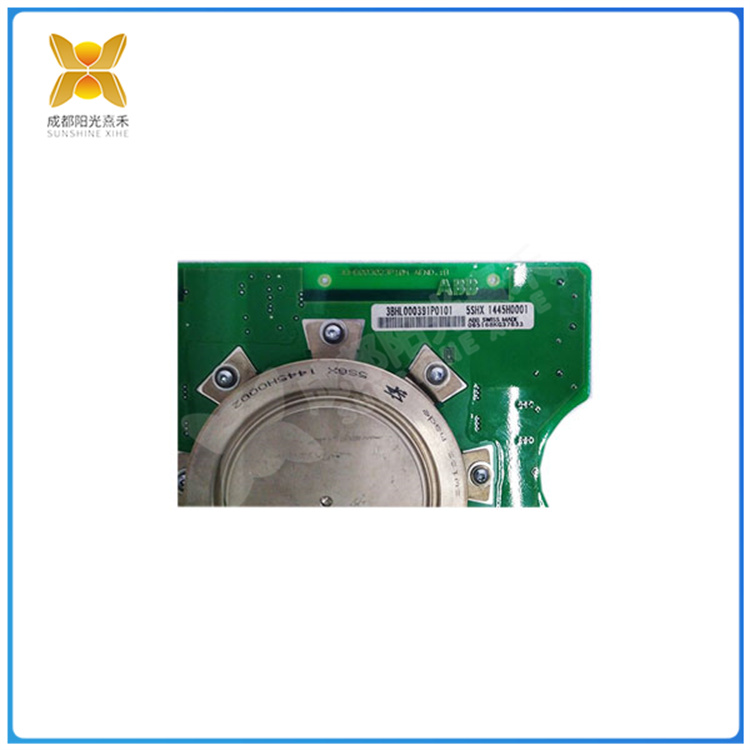
5SHX1445H0001 MOS来控制晶体管的新型电力电子器件
众所周知,IGBT是一种用MOS来控制晶体管的新型电力电子器件,具有电压高、电流大、频率高、导通电阻小等特点,被广泛应用在变频器的逆变电路中。但由于IGBT的耐过流能力与耐过压能力较差,一旦出现意外就会使它损坏。为此,必须对IGBT进行相关保护。一般我们从过流、过压、过热三方面进行IGBT保护电路设计。
IGBT承受过电流的时间仅为几微秒,耐过流量小,因此使用IGBT首要注意的是过流保护。那么该如何根据IGBT的驱动要求设计过流保护呢?
IGBT的过流保护可分为两种情况:(1)驱动电路中无保护功能;(2)驱动电路中设有保护功能。对于第一种情况,我们可以在主电路中要设置过流检测器件;针对第二种情况,由于不同型号的混合驱动模块,其输出能力、开关速度与du/dt的承受能力不同,使用时要根据实际情况恰当选用。对于大功率电压型逆变器新型组合式IGBT过流保护则可以通过封锁驱动信号或者减小栅压来进行保护。
过压保护则可以从以下几个方面进行:
●尽可能减少电路中的杂散电感。
●采用吸收回路。吸收回路的作用是;当IGBT关断时,吸收电感中释放的能量,以降低关断过电压。
●适当增大栅极电阻Rg。
IGBT的过热保护一般是采用散热器(包括普通散热器与热管散热器),并可进行强迫风冷。
新旧型对比
编辑 播报
在传统的使用和设计IGBT的过程中,基本上都是采用粗放式的设计模式,所需余量较大,系统庞大,但仍无法抵抗来自外界的干扰和自身系统引起的各种失效问题。那么该如何突破传统的IGBT系统电路保护设计来解决上述问题呢?
传统保护模式
防护方案防止栅极电荷积累及栅源电压出现尖峰损坏IGBT——可在G极和E极之间设置一些保护元件,如图1的电阻RGE的作用,是使栅极积累电荷泄放(其阻值可取5kΩ);两个反向串联的稳压二极管V1和V2,是为了防止栅源电压尖峰损坏IGBT。另外,还有实现控制电路部分与被驱动的IGBT之间的隔离设计,以及设计适合栅极的驱动脉冲电路等。然而即使这样,在实际使用的工业环境中,以上方案仍然具有比较高的产品失效率——有时甚至会超出5%。相关的实验数据和研究表明:这和瞬态浪涌、静电及高频电子干扰有着紧密的关系,而稳压管在此的响应时间和耐电流能力远远不足,从而导致IGBT过热而损坏。
5SHX1445H0001 MOS来控制晶体管的新型电力电子器件
As we all know, IGBT is a new type of power electronic device using MOS to control transistors, with high voltage, high current, high frequency, small on-resistance and other characteristics, is widely used in the inverter inverter circuit. However, due to the poor over-current resistance and over-pressure resistance of IGBT, once an accident occurs, it will be damaged. Therefore, the IGBT must be protected. Generally, we design IGBT protection circuit from three aspects: overcurrent, overvoltage and overheating.
The time of IGBT to withstand overcurrent is only a few microseconds, and the over-flow resistance is small, so the first thing to pay attention to when using IGBT is overcurrent protection. So how to design overcurrent protection according to the driving requirements of IGBT?
The over-current protection of IGBT can be divided into two cases: (1) there is no protection function in the drive circuit; (2) The protection function is provided in the drive circuit. For the first case, we can set the overcurrent detection device in the main circuit; For the second case, due to the different types of hybrid drive module, its output capacity, switching speed and the bearing capacity of du/dt are different, and it should be properly selected according to the actual situation. The new combined IGBT overcurrent protection for high-power voltage inverters can be achieved by blocking the drive signal or reducing the gate voltage.
Overvoltage protection can be carried out from the following aspects:
● Reduce stray inductance in the circuit as much as possible.
● Absorption loop is adopted. The role of the absorption loop is; When the IGBT is turned off, the energy released in the inductor is absorbed to reduce the turn-off overvoltage.
● Appropriately increase the grid resistance Rg.
The overheating protection of IGBT is generally the use of radiators (including ordinary radiators and heat pipe radiators), and can be forced air cooling.
Contrast between old and new types
Editorial broadcast
In the process of traditional use and design of IGBT, basically the extensive design mode is used, the required margin is large, the system is huge, but it is still unable to resist the interference from the outside world and various failure problems caused by its own system. So how to break through the traditional IGBT system circuit protection design to solve the above problems?
Traditional protection mode
Protection scheme to prevent grid charge accumulation and gate source voltage spike damage IGBT – some protection elements can be set between the G and E poles, the role of the resistance RGE in Figure 1 is to make the grid accumulated charge discharge (its resistance value can be 5kΩ); Two voltage regulator diodes V1 and V2 are in series in reverse to prevent gate source voltage spikes from damaging the IGBT. In addition, the isolation design between the control circuit and the driven IGBT and the drive pulse circuit suitable for the grid are also designed. However, even so, in the actual industrial environment, the above solution still has a relatively high product failure rate – sometimes even more than 5%. Relevant experimental data and research show that this is closely related to transient surge, static electricity and high-frequency electronic interference, and the response time and current resistance of the regulator in this is far from enough, resulting in overheating and damage of IGBT.

购买咨询热线/Phone:18859254943
邮箱/Email:sales@ygdcs.com
地址:成都高新区天益街北巷52号附14号2层

 购买咨询热线/Phone:
 邮箱/Email:
 地址:
地址:
