


 购买咨询热线/Phone:
 邮箱/Email:
 地址:
地址:Description
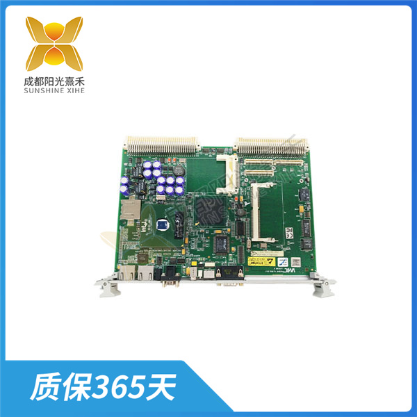
VMIVME-7740-850 常开触点表示触点常开,不允许任何电流通过
继电器输出逻辑模块是一种能够实现继电器输出逻辑控制的模块,VMIVME-7740-850可以用于各种控制系统中,如电力、IDC机房、工业、智慧城市、楼宇等行业。
继电器输出逻辑模块通常具有以下特点:
– 实时性强:能够实现实时控制。
– 可靠性高:具有高可靠性,能够保证系统的稳定运行。
– 可编程性:提供了易于使用的编程接口,可以根据用户的需求进行编程。
继电器输出逻辑模块的工作原理如下:
继电器是一种由少量电流操作的开关,有两个触点,分别是常开(NO)和常闭(NC)。当施加小的电信号时,触点中的状态变化就会发生。
继电器输出逻辑模块的核心是继电器逻辑电路,VMIVME-7740-850显示各种组件、连接和输入输出的关系。逻辑电路中使用特定的符号表示不同的电路元件。例如,常开触点表示触点常开,不允许任何电流通过;常闭触点表示触点允许电流通过。
在继电器逻辑电路中,触点NO和NC用于指示常开或常闭继电器电路。VMIVME-7740-850包含两条垂直线,一条在最左边,另一条在最右边。这些垂直线称为导轨。最左边的轨处于电源电压电位并用作输入轨,最右边的轨处于零电位并用作输出轨。
当P0.8脚为低电平时,光耦PC817输入端的发光二极管导通发亮,使得光耦输出端的光电接收三极管接收到光信号导通。接着,NPN三极管Q1基极会形成高电平使其导通。此时电流顺利通过继电器输入端的电磁线圈产生磁场,继电器右端的开关被吸到3脚,使得3,5两脚相连。从P2接线端子上看就是1,2脚相连,2,3脚断开。
反之,如果P0.8脚为高电平,光耦输出端的接受三极管无法导通,则三极管Q1也无法导通,电流无法通过继电器的电磁线圈。由于没有受到磁力作用,开关则被弹回2脚。从P2接线端子上看,就是1,2脚断开,2,3脚相连。
此外,在继电器电路模块中,可以通过把左下角LED1的阴级与控制器引脚相连(如图中与单片机P0.8引脚相连),从而可以通过控制引脚的高低电平来驱动继电器的开合。
总的来说,继电器输出逻辑模块工作原理主要是通过改变输入信号的电平状态来控制继电器的开合状态,从而实现逻辑控制功能。
VMIVME-7740-850 常开触点表示触点常开,不允许任何电流通过
Relay output logic module is a module that can realize relay output logic control, VMIVME-7740-850 can be used in a variety of control systems, such as power, IDC room, industry, smart city, building and other industries.
Relay output logic modules usually have the following characteristics:
– Strong real-time: can achieve real-time control.
– High reliability: High reliability to ensure the stable operation of the system.
– Programmability: provides an easy-to-use programming interface that can be programmed according to user requirements.
The relay output logic module works as follows:
A relay is a switch operated by a small amount of current and has two contacts, normally open (NO) and normally closed (NC). When a small electrical signal is applied, a state change in the contact occurs.
The core of the relay output logic module is the relay logic circuit, and the VMIVME-7740-850 shows the relationship between various components, connections and input and output. Specific symbols are used in logic circuits to represent different circuit elements. For example, normally open contact means that the contact is normally open and does not allow any current to pass through; Normally closed contact indicates that the contact allows current to pass through.
In a relay logic circuit, contacts NO and NC are used to indicate normally open or normally closed relay circuits. The VMIVME-7740-850 consists of two vertical lines, one on the far left and the other on the far right. These vertical lines are called guides. The leftmost rail is at the supply voltage potential and is used as an input rail, and the rightmost rail is at zero potential and is used as an output rail.
When the P0.8 pin is low voltage, the light-emitting diode at the input end of the optocoupler PC817 is illuminated, so that the photoreceiving triode at the output end of the optocoupler receives the optical signal. Next, the NPN triode Q1 base forms a high level to enable it to be switched on. At this time, the current smoothly generates a magnetic field through the electromagnetic coil at the input end of the relay, and the switch at the right end of the relay is sucked to pin 3, so that the two pins 3 and 5 are connected. From the P2 terminal, it can be seen that pins 1,2 are connected, and pins 2,3 are disconnected.
On the contrary, if the P0.8 pin is high, the accepting triode at the optocoupler output can not be switched on, the triode Q1 can not be switched on, and the current cannot pass through the relay’s electromagnetic coil. Since there is no magnetic force, the switch is bounced back to the 2 pins. From the point of view of the P2 terminal, that is, feet 1,2 are disconnected, and feet 2,3 are connected.
In addition, in the relay circuit module, the negative level of LED1 in the lower left corner can be connected to the controller pin (as shown in the figure and the P0.8 pin of the MCU), so that the opening and closing of the relay can be driven by controlling the high and low level of the pin.
In general, the working principle of the relay output logic module is mainly to control the opening and closing state of the relay by changing the level state of the input signal, so as to achieve the logic control function.

 购买咨询热线/Phone:18859254943
- 邮箱/Email:sales@ygdcs.com
- 地址:成都高新区天益街北巷52号附14号2层


